IN-12A Nixie Tube Clock
Summary
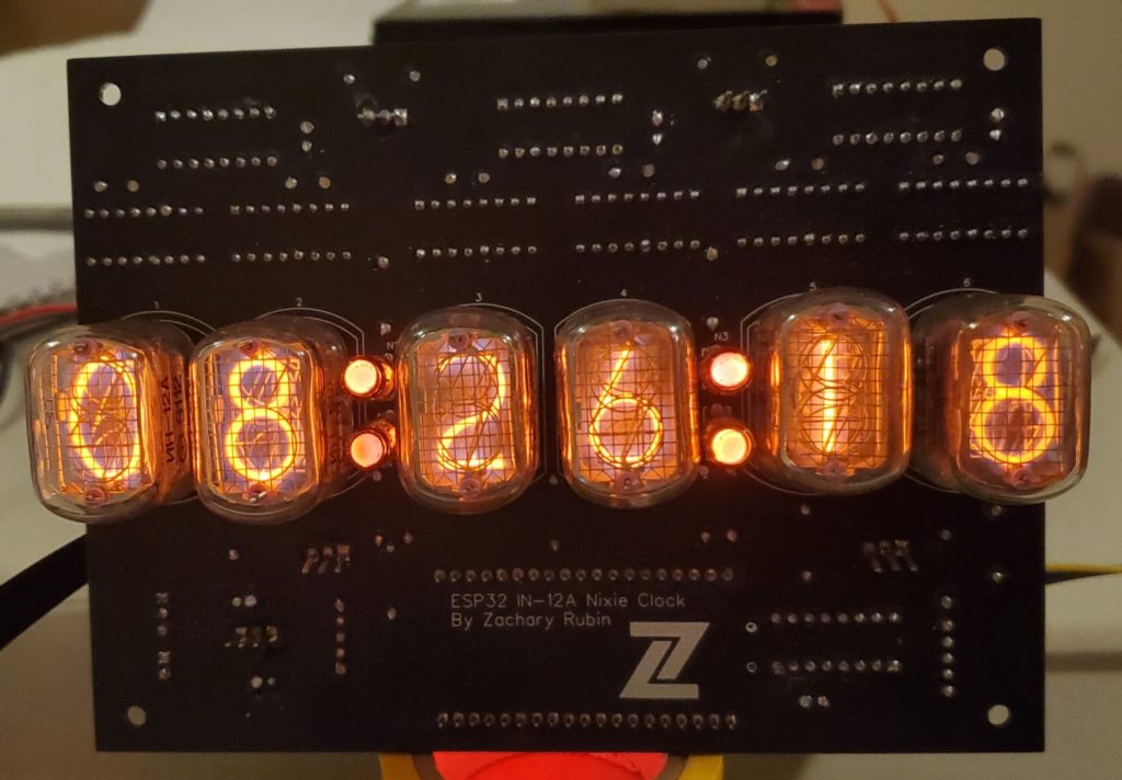
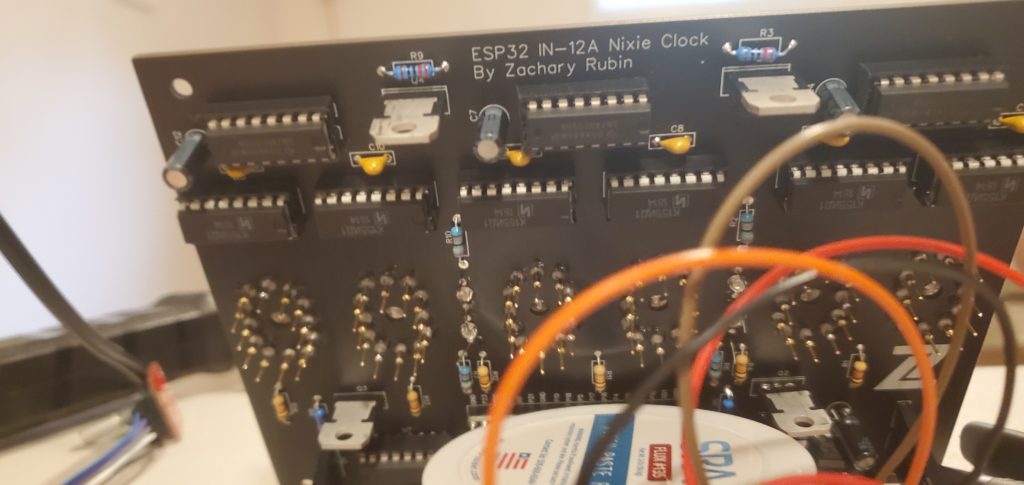
I managed to complete my first major embedded development project: a nixie tube clock. A nixie tube is a display device invented in the 1950s that is typically used to show numerals. Nixie tubes illuminate the current digit using a bright glow discharge.
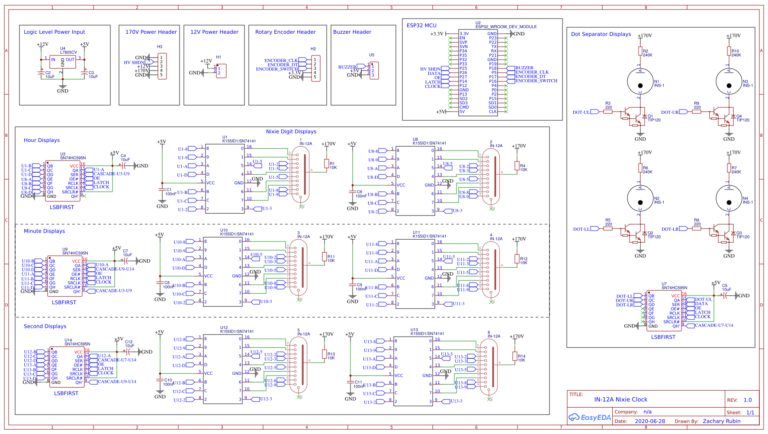
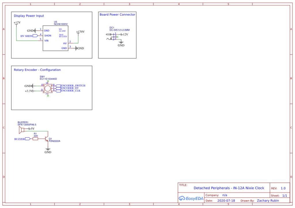
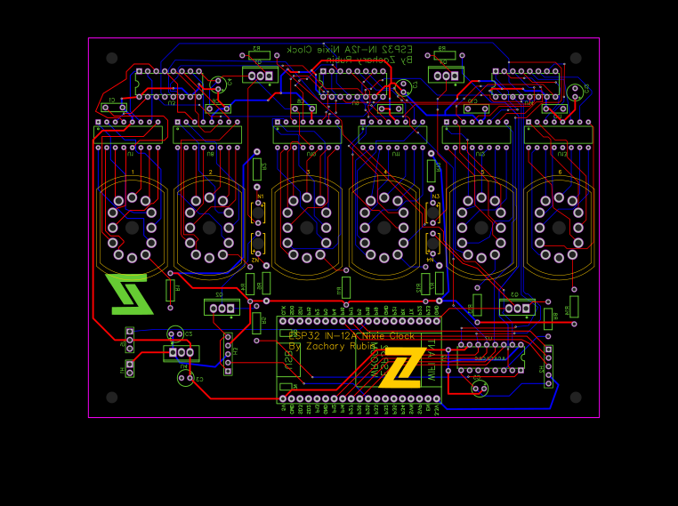
In this post I will go over the entire process I went through to create the clock, from initial hardware experimentation through programing the microcontroller.
Initial Hardware Experimentation
Lighting Up A Nixie Tube
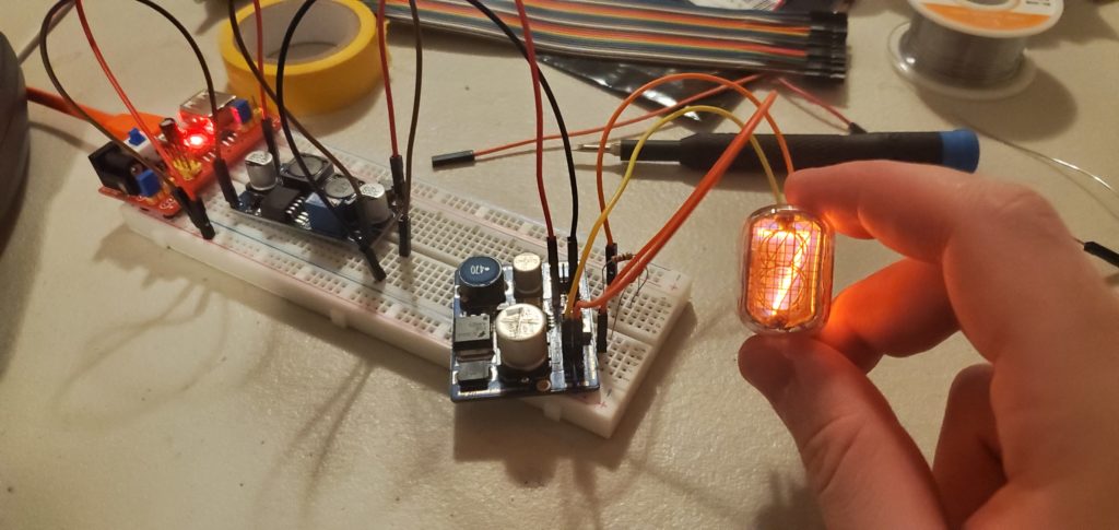
The first task to work through was figuring out how to light up one of the digits of a nixie tube. Unfortunately, a nixie tube isn’t as easy to work with as an LED; you can’t just connect a nixie tube to a 5V power supply with a resistor and expect it to work. Nixie tubes require high voltage to turn on. According to the datasheet of the IN-12A – the nixie tube i decided to use – the nixie tube requires 170 volts to turn on! For reference, a wall outlet in a North American home supplies 120 volts.
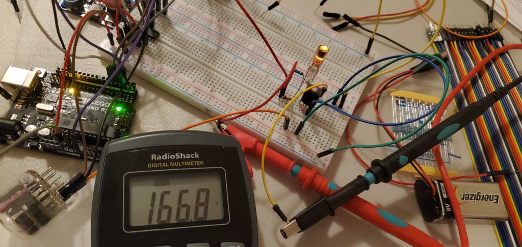
To supply the nixie tube with the required voltage, I bought a high voltage DC power supply designed for nixie tubes. The power supply can boost a 12V input up to 235V. When I was trying to first turn on a nixie tube, I did not have a 12V input for the high voltage power supply. I ended up using the 5V supply from a USB cable as an input to a boost converter outputting 12V. I then used this 12V output as the input to the high voltage power supply. I was able to to power on the nixie tube with 166.8V, slightly less than what the data sheet recommends. I decided to keep this voltage output to the nixie tubes for the final clock design. With resistance kept equal, a lower voltage means lower current running through the nixie tube. A lower current will extend the lifetime of the nixie tubes in the clock.
Extra Photos
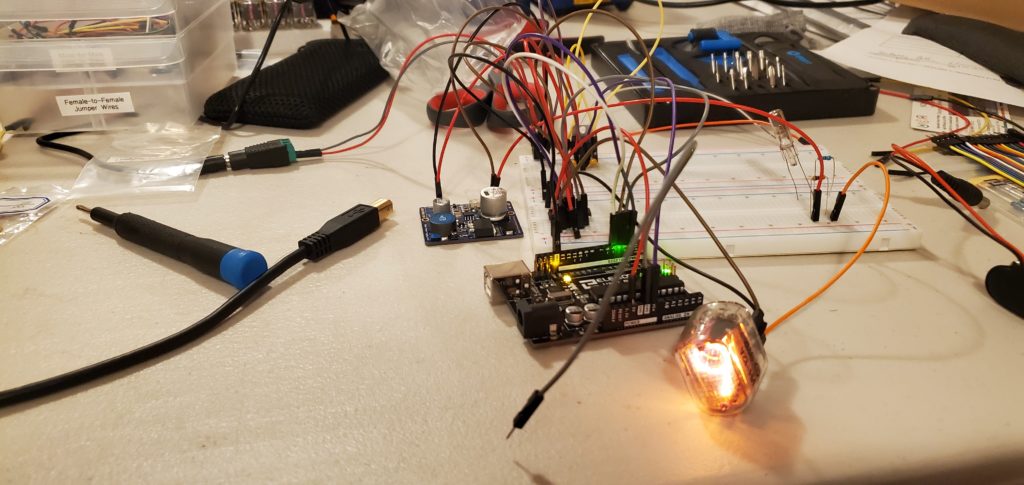
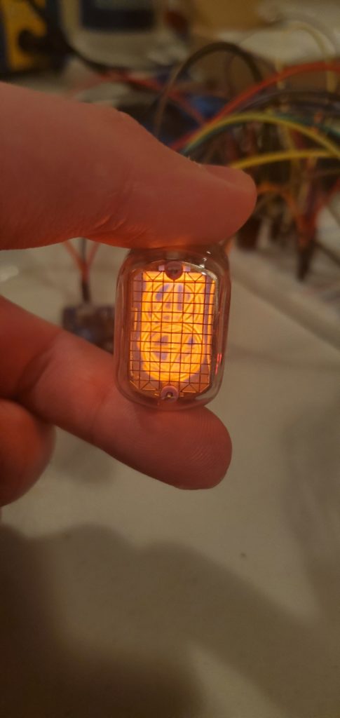
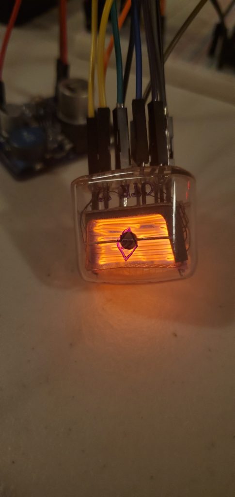
I wanted to see what a nixie tube looked like when all the digits were turned on. From the front, all the digits blur together into a jumbled mess. In the front view picture below, I can barely make out the "3" and the "6" digits. From the side, the physical difference in location of each digit is very evident. The digits appear as a column of light with small gaps in between.
 |
 |
|---|
- Nixie Tube Digit Cycle
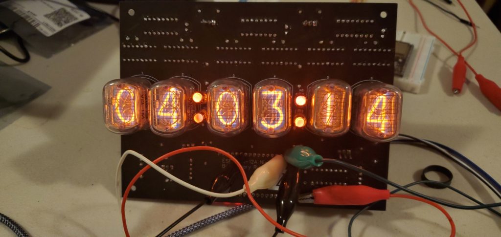
- Nixie Clock - Full Display Transition
- Nixie Clock - Slot Machine Digit Cycle
- Nixie Clock - Options Menu & Timer Mode
